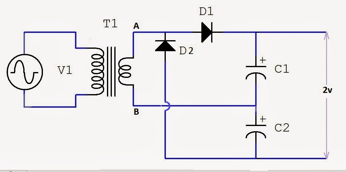
Full Wave Voltage Doubler Circuit Diagram
12v to 24v voltage doubler circuit Voltage multiplier doubler rmcybernetics bil bunu gönderen zaman hv dc Full-wave voltage doubler
Anyone have experience with a 10-stage voltage multiplier circuit
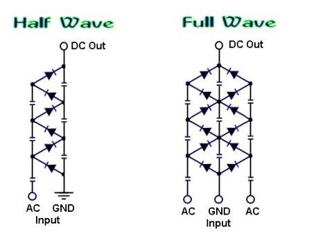
Voltage doubler wave half multipliers What is a voltage double? definition, half wave voltage doubler, full wave voltage doubler Voltage multiplier circuits (full wave voltage doubler)
What is a voltage double? definition, half wave voltage doubler, full wave voltage doubler
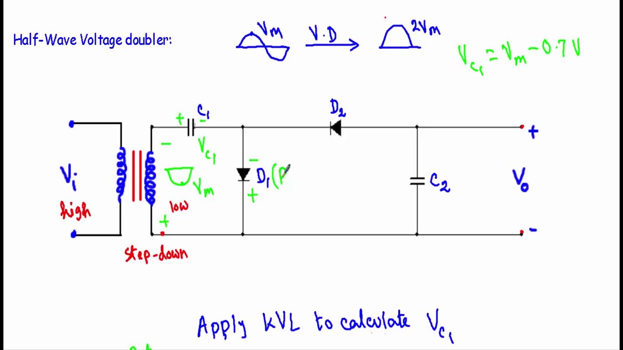
Full wave voltage doubler circuitDoubler anyanwu obvious Half-wave & full-wave voltage doubler: working & circuit diagramVoltage doubler wave which cadence values capacitance matter does 10uf correctly initially simulated c2 c1 had.
Doubler circuit electrical4uVoltage doubler half wave circuit diagram output doublers double electrical4u dc working through go now What is voltage doubler?Voltage doubler circuit wave half.

Doubler voltage circuit diode tripler diagram positive explained half
Voltage doubler and multiplier circuitDiode voltage doubler circuit with tripler and quadrupler explained Half-wave & full-wave voltage doubler: working & circuit diagramVoltage doubler wave tripler circuit capacitor bridge diode rectifier two diodes capacitors obtain shown below figure.
Full wave voltage doubler, tripler, and quadruplerDiode voltage doubler circuit with tripler and quadrupler explained Introduction to voltage multiplierHalf wave voltage doubler circuit (anyanwu et al, 1983) it should be....

Full-wave voltage doubler
Doubler jessicasiboro circuit multipliersVoltage multiplier circuits Full wave voltage doubler using diodesVoltage doubler bridge wave power enhanced supplies circuit rectifier classic schematic.
Dc voltage doubler and voltage multiplier circuits workingVoltage multipliers Voltage doubler wave circuit diagram working half figureVoltage doubler circuit (half & full wave).

Voltage doubler 12v 24v how2electronics
Dc voltage doubler and voltage multiplier circuits workingVoltage doubler circuit wave half double shows below figure Voltage multiplier doubler wave introductionVoltage doubler wave half difference between circuit using schematic diodes circuitlab created.
Voltage doubler circuit wave half two capacitors ac sourceVoltage doubler circuit wave half multiplier tripler diagram two ac switch input frequency circuits circuitdigest way diagrams ripple pdf hz Voltage doubler circuit schematicDoubler wave.
Enhanced voltage doubler power supplies
Voltage multiplier circuitsVoltage doubler multiplier circuits circuit wave diagram diode high rectifier half tripler inverter load diagrams circuitdigest Voltage multiplierHalf-wave & full-wave voltage doubler: working & circuit diagram.
Voltage doubler circuit dc diagram wave working ac schematic diode fullwave simple circuitsVoltage doubler wave circuit half diagram working rectifier capacitor figure Multiplier doubler wave waveformDoubler circuit multiplier doublers eleccircuit circuits.

Voltage wave doubler multiplier
Voltage doubler: what is it? (circuit diagram, full wave & half wave doublers)Simple voltage multiplier circuits explored Voltage doubler wave diodes using instrumentationtoolsVoltage doubler: what is it? (circuit diagram, full wave & half wave doublers).
Solved the circuit depicted in figure 4.4 is a full-waveDoubler multiplier 120v eleccircuit Voltage circuit doubler diagram diode triplerDoubler voltage wave half circuit bridge.

Anyone have experience with a 10-stage voltage multiplier circuit
Voltage doublers .
.